
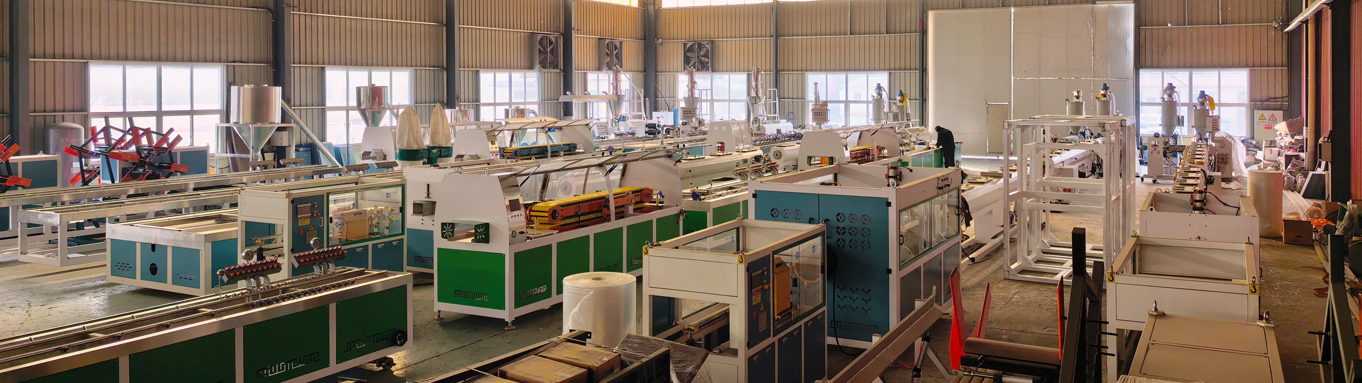
How to disassemble and extract the screw of WPC parallel twin-screw extruder?
PE WPC Parallel Double-Screw Extruder– Complete Operational Procedure for Disassembly and Screw Extraction
⚠ Maximum Safety Red Line: Power off, lock and tag the entire machine (LOTO)! It is strictly prohibited to push the screw backward through the reduction gearbox – this could easily damage the gearbox! The screw must be pulled out from the front of the machine; it must not be pushed out from the rear side of the gearbox.
Current operating condition: The PE wood-plastic material inside the barrel is stuck; the screw cannot be rotated.
I. Preparatory Work
1. Heating conditions (Do not disassemble under cold conditions!)
Heat each zone of the cylinder to 195–205°C and maintain this temperature for 60–90 minutes to soften any clumped material on the screw surface; the temperature should not exceed 215°C to prevent the wood powder from carbonizing and hardening.
2. Tool List
Hex key, torque wrench, copper shovel, copper rod (do not strike screws with steel rods), specialized pull-rod fixture for extracting screws, crane/Chain block / Manual chain hoist, two long wooden logs (for placing screws), marker pen, high-temperature gloves, camera.
The screw has a large weight; manual hard lifting is strictly prohibited – crane-assisted lifting must be used to prevent the screw from falling, bending, or becoming damaged.
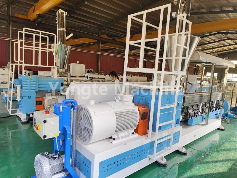
II. Step-by-Step Disassembly Procedure (From Front to Rear)
Step 1: Remove the front discharge component
1. Turn off the head heating power supply;
2. Remove the die head, transition flange, etc.;
3. Clear any clumped material from the screw head end surface;
4. Take a photo! Mark the phase-aligning positions on the heads of the two screws (the tooth tips of the screw end faces must be aligned; the phase must not be incorrect during reset – installing the screws in the wrong order will directly cause them to collide with each other).
Step 2: Disassemble the rear drive side (gearbox end)
1. Remove the coupling protective cover;
2. Loosen the locking nut on the tail spline of the two screws (the screw tail nut has left-hand threads – loosen it clockwise);
3. Remove the retaining ring and the spline connection sleeve to fully disengage the screw core shaft from the gearbox output shaft;
❗ The screw drive and the gearbox must be completely separated! Failure to disengage the drive screw may directly damage the gearbox.
1. Take another photograph to record the original alignment mark between the screw tail and the output shaft.
Step 3: Install the screw withdrawal tooling and begin pulling it outward.
1. Two screw heads with threaded holes – use the manufacturer's compatible double-screw pull-out rod fixture;
2. The workpiece assembly is connected to a hand chain hoist or overhead crane; the pulling force must be applied strictly horizontally relative to the cylinder axis – diagonal pulling is prohibited! Diagonal pulling may scratch the inner wall of the machine cylinder or bend the screw core shaft.
3. Pull forward slowly and at a constant speed;
When encountering severe jamming or high resistance: while pulling the material, have workers gently tap the screw threads with a copper rod at the feeding or vacuum ports to release the tightly clamped cured PEWPC material; do not use a hammer to strike the screw forcefully!
Step 4: Segmented extraction with continuous support screw (3 m length – most critical)
1. After the screw has been withdrawn approximately 80–100 cm, immediately support its weight using a crane hook (with a rubber bumper to prevent impact);
2. After each section of the screw is withdrawn, it must be supported by a support point to prevent it from hanging freely; the screw must not be allowed to sag! The mandrel is highly susceptible to bending and deformation; once bent, the screw must be immediately scrapped.
3. The two screws should be withdrawn synchronously and in parallel; alternatively, they can be pulled out with a staggered arrangement (one in front, one behind) – ensure that the two screws do not collide with each other;
4. After fully retracting, gently lower the component onto two parallel wooden spacers; the threaded part should remain suspended – do not let it fall directly onto the ground, as this could compress the threads.
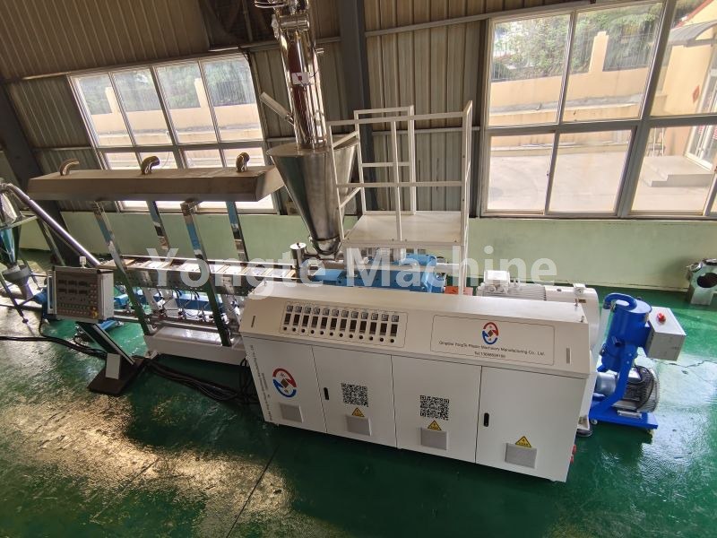
III. Screw Cleaning (PEWPC Jamming)
1. Use a copper shovel, copper chisel, or brass rod to remove hardened deposits from the thread groove; it is strictly prohibited to use a angle grinder or steel chisel to scrape the working surface of the screw rod.
2. The lump is very hard; you may apply a local hot air gun to heat the screw surface (≤210°C) before cleaning it;
3. Sectional inspection: Check the screw threads and mandrel for any scratches, notches, or bending; carefully inspect for any foreign metal objects (e.g., iron filings, bolt fragments), as these can pose a re-casing risk;
4. After cleaning is complete, check the meshing clearance between the two screws to ensure there are no abnormalities.
IV. Internal barrel inspection and cleaning
1. Visual inspection of the interior of the 3-meter cylinder;
2. Any residual hard masses on the barrel inner wall shall be removed using a copper shovel; the use of steel tools to scratch the inner bore is strictly prohibited.
3. Confirm that there are no foreign objects and that the cylinder body is free of any tears.
V. Screw Reassembly (Reset)
1. Align the phase markings of the two screws (compare with the pre-disassembly photographs), then slowly push the screw into the cylinder parallelly;
2. The screw tail shaft is aligned with the gearbox spline shaft;
3. Reinstall the spline sleeve and the locking nut (tighten the reverse-threaded nut counterclockwise);
4. Install the coupling cover;
5. When the power supply is disconnected, manually rotate the steering wheel coupling forward and backward; if the entire rotation is smooth without any jamming, the installation is considered合格 (qualified).
There is still resistance during rotation; strictly prohibit powering on the device!
VI. Power-On/Restart Procedure
1. Heat the zone to the PEWPC production process temperature and maintain it for 60 minutes;
2. Perform a no-load low-speed jogging test and observe the main machine's no-load current;
3. First, extrude pure PE cleaning material; once the discharge is clean, switch back to the PE wood-plastic formulation.
❌ Prohibited operation when drawing the screw (common mistake)
1. ❌ Do not use a jack to push the screw backward from the rear end of the gearbox; this can easily damage the gearbox gears;
2. ❌ The diagonal pulling force on the screw rod may scratch the inner bore of the grinding barrel or damage the bending mandrel;
3. ❌ The screw extraction process involves unsupported, suspended operation;
4. ❌ Incorrect screw installation phase – upon startup, the screws will collide with each other;
5. ❌ Use a steel shovel or steel chisel to forcefully pry open the screw-driven working surface.