
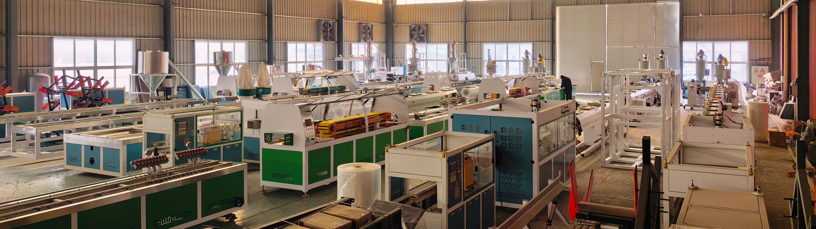
How to Adjust Screw Spacing of Conical Double Screw Extruder?
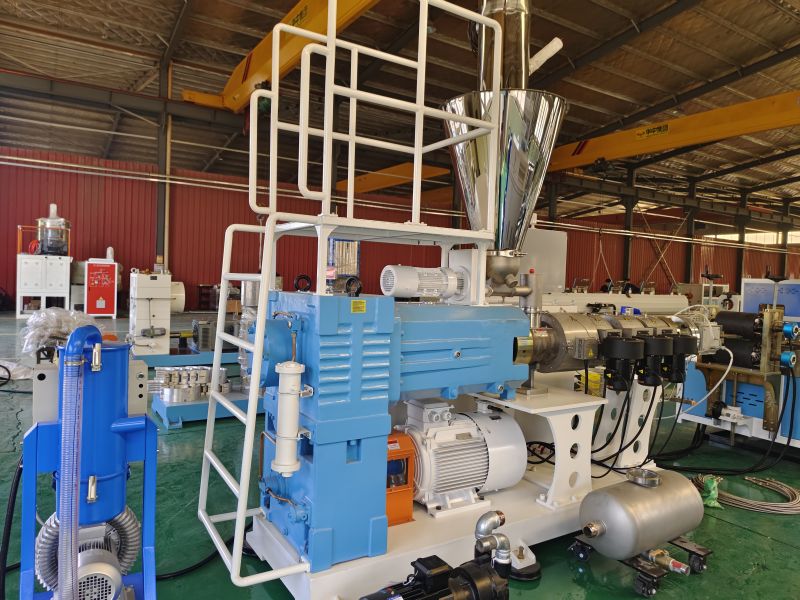
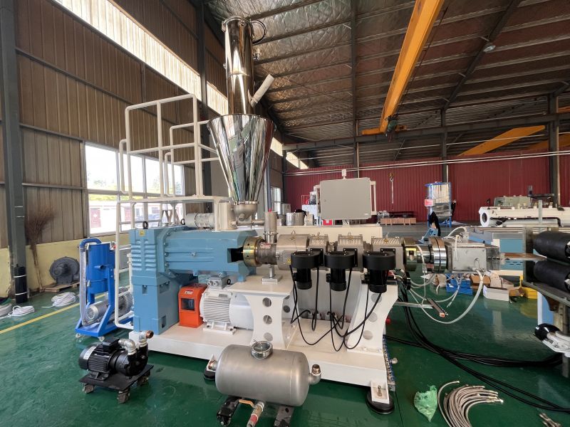
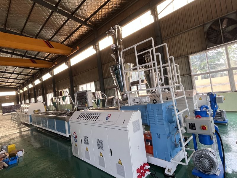
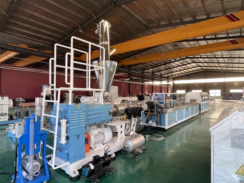
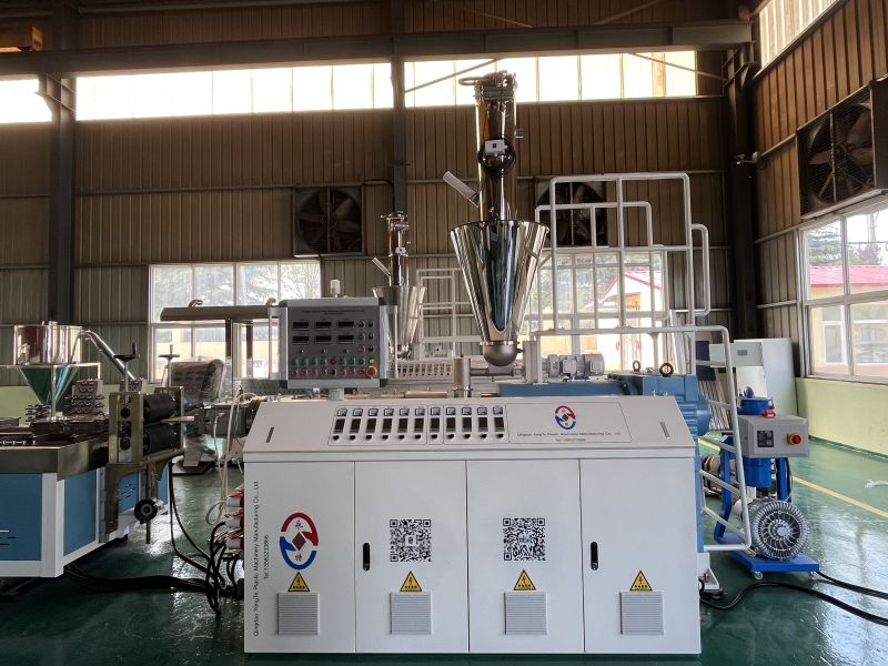
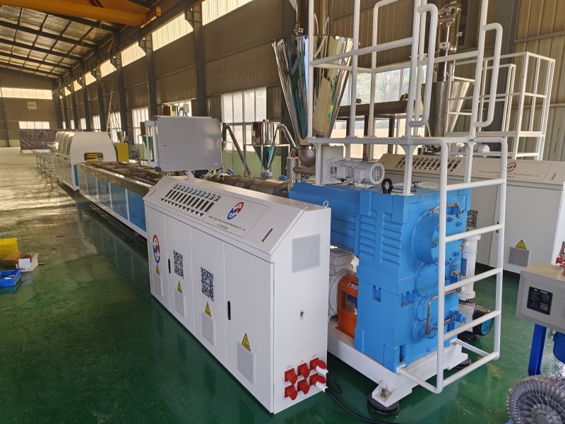
Adjustment for Screw Spacing of Yongte SJSZ65/132 PE-PP Wood-Plastic Composite Conical Twin-Screw Extruder
I. General Principles of the Plan
This solution is designed for the Yongte SJSZ65/132 conical twin-screw extruder to accommodate PE-wood-plastic (PE + wood powder + additives) modified extrusion processes, and standardizes the adjustment procedures for the screw's axial and radial meshing gaps, as well as the gap between the screw and the barrel. PE-wood-plastic materials contain wood fibers, exhibit poor fluidity, and generate high frictional heat; deviations in the screw gap can directly lead to issues such as uneven discharge, melt sludging, product foaming, screw wear, and abnormal equipment noise. Precise gap adjustment is therefore a critical process for ensuring both the quality of wood-plastic products and the service life of the equipment.
This solution is applicable to scenarios such as new machine installation, screw/cylinder replacement, long-term wear maintenance, and troubleshooting of discharge abnormalities; it strictly adheres to Yongte Equipment's original factory assembly standards and the requirements for the wood-plastic extrusion process.
II. Core Adjustment Standards (PE-Composite Specific)
Based on the parameters of the SJSZ65/132 model and the properties of wood-plastic composites, this solution defines clear gap standards to distinguish it from conventional plastic extrusion processes and ensure compatibility with high-filler wood powder applications:
1. Radial clearance between the screw and the barrel
Feed large end: 0.30–0.35 mm; discharge small end: 0.25–0.30 mm; the entire assembly is uniform with no local wear clearance; for Model 65, the standard rearward adjustment stroke is 6–8 mm.
This clearance range effectively balances the risk of shear heat accumulation associated with the high friction and low fluidity characteristics of wood-plastic composites, preventing both melt retention and decomposition caused by excessively small clearances, as well as backflow or leakage resulting from excessively large clearances. During adjustment, the inner bore of the barrel should serve as the reference point; a specialized feeler gauge should be used to perform multi-point measurements along the entire length of the screw, ensuring that the conical transition section exhibits no abrupt steps. For barrels that have undergone wear repair, the actual inner diameter must be re-measured, and the theoretical clearance value must be corrected to prevent secondary adjustment deviations caused by inaccurate reference measurements.
2. Double-screw meshing clearance
The axial front-rear clearance is uniform; the meshing radial clearance ranges from 0.08 to 0.12 mm; there are no rubbing contacts or excessive leakage gaps, ensuring thorough mixing and compaction of the wood-plastic melt.
The control of meshing clearance must be performed under cold conditions; a high-precision dial indicator, combined with specialized fixtures, should be used to measure the relative displacement during the synchronous rotation of the two screws, ensuring that the clearance fluctuation across the entire meshing section does not exceed ±0.02 mm. During the adjustment process, priority should be given to correcting the backlash of the driving gear, followed by fine-tuning of the axial position of the driven screw; this prevents the occurrence of false meshing due to gear transmission errors. For conical twin-screw systems, particular attention must be paid to the continuity of the clearance in the transition zone between the compression section and the metering section, to prevent the wood powder enrichment zone from experiencing localized disengagement, which could lead to sudden expansion of the melt channel and subsequently cause material bridging or degradation. After each adjustment, the system should be manually rotated for at least three full turns to confirm the absence of jamming or periodic resistance variations before proceeding to the next process step.
3. Axial play
The total axial play of the twin-screw system is ≤0.03 mm; the play between the two screws is balanced, with no unilateral offset or jerking.
The clearance detection shall be performed under the condition where the screw rods are fully assembled. Use a magnetic mounting base to secure a dial indicator to the flange end face of the cylinder; position the probe perpendicular to the shoulder end face of the screw rod, manually push or pull the screw rod axially, and record the maximum displacement value. If the clearance exceeds the allowable tolerance, inspect whether the thrust bearing preload is uniform and whether the locking nut is loose, then adjust the shim thickness to restore the design clearance. After adjustment, repeat the turntable test to ensure that both screw rods can still move synchronously and smoothly under axial loading conditions, thereby preventing the generation of additional stresses or seal failure during operation due to differential thermal expansion.
4. Calendering gap
The screw's large end has a diameter of 1.5 mm and its small end has a diameter of 1.0 mm; these dimensions are optimized for the compression ratio of wood-plastic composites, thereby preventing insufficient plasticization or overheating-induced decomposition.
This clearance value must be measured under cold conditions using a feeler gauge or a specialized gauge to ensure that there is no contact between the screw end face and the calendering plate, and that this clearance is distributed uniformly. If the measured value deviates from the specified range, correction should be performed by adding or removing adjustment washers or by grinding the mounting surface of the calendering plate; it is strictly prohibited to force tightening, as this may cause deformation of the screw. After adjustment, a material-in-process validation must be conducted based on the material properties, observing the surface finish of the extruded product and the fluctuations in melt pressure to confirm that the plasticization quality remains stable.
III. Pre-adjustment Preparation Work
1. Equipment Shutdown and Safety Protection
Completely shut down the equipment, disconnect the main power supply, hang maintenance warning signs, and shut off the temperature control, feeding, and traction systems. Wait until the barrel temperature drops below 80°C to prevent high temperatures from causing burns or residual carbonization of the material that could affect measurement accuracy, and release any residual pressure within the equipment.
2. Equipment Cleaning and Inspection
Remove the machine head, multi-hole plate, and filter screen; thoroughly clean the interior of the cylinder of any residual wood-plastic residue, charred material, or impurities; inspect the screw rod and inner wall of the cylinder for no scratches, tooth fractures, or severe wear; and verify that the spline shaft, connecting sleeve, and bearings are secure and undamaged. Confirm that the lubricating oil level in the gearbox is normal, the oil quality is clean, and there are no emulsions or impurities present.
3. Preparation of Tools and Consumables
0.02–1.0 mm high-precision feeler gauge, dial indicator, depth micrometer, stainless steel adjustment shim (specifications: 0.01/0.05/0.1 mm), torque wrench, copper rod, dust-free cloth, alcohol, spare sealant, and fastening bolts.
4. Pre-state validation
Perform manual turning to confirm that both screws rotate smoothly without any jerking or metallic friction noise; test the free movement of the screws: when one screw is tightened, the other should be able to move freely forward and backward without axial jamming or misalignment; only after these conditions are met may gap adjustment work proceed.
IV. Detailed Adjustment Procedure Steps
Step 1: Zeroing the gearbox axial reference
1. Loosen the tail-end locking nut of the main and driven screws from the connecting sleeve; push the distribution gear shaft to the state of zero axial clearance to eliminate the axial play of the gearbox.
2. Tighten both the driving and driven screws separately until the screw spline sleeve fully engages with the distribution shaft, ensuring that the axial reference lines of both screws are aligned and there is no offset or clearance.
3. Manually rotate the drive unit 3–5 times to confirm that the twin screws are meshed without interference and show no axial displacement; then lock the reference position.
Step 2: Measurement and adjustment of the radial clearance between the screw and the barrel
1. Collect segmented samples from the barrel feeding port and discharge port; uniformly select four points—upper, lower, left, and right—along the screw circumference; use a feeler gauge to measure the radial clearance at both the large end and the small end; and record the data obtained from each point.
2. Excessive clearance: Add a stainless steel gasket of the corresponding thickness at the rear end of the screw to push the screw forward and reduce the radial clearance; 3. Insufficient clearance: Reduce the thickness of the gasket and appropriately move the screw backward to prevent the screw from rubbing against the cylinder and avoid high-temperature wear.
3. Perform repeated fine adjustments of the gaskets to ensure that the clearances at both the large and small ends fully comply with the specified standards, with the clearance variation across all sides of the same cross-section being ≤ 0.03 mm, and no offset in clearance.
Step 3: Double-screw meshing clearance calibration
1. Fix the position of the driving screw, manually fine-tune the axial position of the driven screw, measure the front-to-back meshing clearance between the screws, and ensure that the front-to-back clearance is uniform and consistent.
2. Deviation correction: When the front-end clearance is excessive, a shim should be added and shifted forward at the rear end of the driven screw; when the rear-end clearance is excessive, a fine-tuning shim should be added and shifted forward at the rear end of the driving screw, ensuring that the meshing of the twin screws always remains centered and symmetrical.
3. After completing the adjustment, use a screwdriver to rotate the twin screws, and check the uniformity of the axial displacement throughout the entire range; ensure there is no unilateral jamming or any abnormal deviation.
Step 4: Precise calibration of axial play
1. Mount the dial indicator securely to the end face of the barrel; align the indicator head vertically against the end face of the screw; manually push and pull the screw, and read the maximum displacement value.
2. By adjusting the number of tail-end balancing gaskets, the axial play of the twin screws is controlled at ≤0.03 mm, and the play difference between the two screws is limited to ≤0.01 mm, ensuring stable operation without vibration.
Step 5: Full Locking and Reset
1. Once all gaps meet the specified requirements, uniformly tighten the rear locking nut and the connecting sleeve; ensure the torque is evenly distributed to prevent any single-sided over-tightening that may cause the screw rod to shift.
2. Perform a full manual turning inspection again to confirm that there is no metal friction, no jerking, and that the clearance remains stable without any changes.
3. Clear the work area; reset the machine head, filter screen, and porous plate; and inspect all sealing points to ensure they are in good condition and free of any potential leaks of material or oil.
V. Heating Test and Process Calibration (for PE-wood composites)
1. Heating preheating
Implement a staged heating process: the first zone of the barrel is set at 160°C, the second zone at 170°C, the third zone at 175°C, and the die head at 180°C; maintain these temperatures for 30 minutes to ensure uniform temperature distribution throughout the machine body, eliminate the impact of thermal expansion and contraction on the clearance, and prevent the clearance from meeting specifications during cold operation or causing contact between the die and the barrel during hot operation.
2. No-load test run
Run at low speed under no-load conditions for 10 minutes; observe that the equipment exhibits no abnormal noise, no vibration, and no abnormal temperature rise; the gearbox and bearings operate smoothly, and the screw rotates uniformly.
3. Material-equipped trial production verification
Feed low-speed PE-wood composite material; gradually increase the main machine's rotational speed and observe the discharge condition: the discharge should be uniform, free of streaks, bubbles, or charred material; the melt should be fully plasticized and compacted to be considered qualified. If leakage, poor plasticization, abnormal noise, or vibration occurs, immediately stop the machine and re-perform the gap fine-tuning.
VI. Common Faults and Gap Adjustment Solutions
|
fault phenomenon |
Core Causes |
Rectification and Adjustment Methods |
|
Uneven material discharge, edge material deficiency, and low output |
The screw meshing clearance is too large, the radial clearance is excessive, resulting in material backflow and leakage. |
Fine-tune the shim at the screw tail end to reduce both meshing clearance and radial clearance, ensuring uniform clearance distribution. |
|
The melt slurry or products exhibit yellowing with burnt marks, and the barrel temperature shows an abnormally high increase. |
If the clearance is too small, excessive friction between the screw and the barrel will cause the wood powder to undergo high-temperature decomposition. |
Appropriately reduce the bearing clearance to increase the gap, thereby reducing shear friction and verifying the stability of the thermal engine's clearance. |
|
Abnormal equipment noise, vibration, or periodic stalling of the screw mechanism |
Excessive axial play, meshing clearance, or unilateral contact between the screw and the cylinder |
Calibrate the axial runout, adjust the meshing clearance before and after, and eliminate the misalignment-induced wear gap. |
|
Internal bubbles in the product and plasticizing porosity |
The calendering gap exceeds the specified limit, and the mixing and compaction process is insufficient. |
Calibrate the big-end and little-end calendering gaps to match the compression ratio of the wood-plastic composite material. |
VII. Precautions and Maintenance Guidelines
1. Gap adjustment must be performed while the machine is cold; under hot-machine conditions, the gap may experience significant thermal expansion deviations. High-temperature gap adjustment is strictly prohibited to prevent damage to the screw and barrel.
2. Gaskets must be flat, clean, and free of burrs or impurities; adjustments to gasket thickness should be made incrementally—each fine adjustment shall not exceed 0.05 mm, and significant adjustments are strictly prohibited.
3. Under high-fill PE-wood composite operating conditions, the material exhibits strong wear characteristics; therefore, the clearance should be re-measured after every 3 months, and a full calibration should be performed annually to prevent clearance from exceeding the permissible limits due to prolonged wear.
4. The locking bolts must be tightened uniformly in a diagonal pattern to prevent the threaded rod from being subjected to force-induced displacement, which could lead to localized rubbing and wear.
5. It is strictly prohibited to perform empty rotation without material, high-speed hard start-up, or low-speed operation during the gap adjustment trial run phase; protective measures must be implemented to safeguard the meshing tooth surfaces and the screw coating.
VIII. Acceptance Criteria
1. All clearance parameters comply with the standards specified in this specification; the clearances at all points are uniform, and the deviations fall within the allowable range.
2. Under no-load conditions and during material-fed operation, there shall be no metallic abnormal noise, no vibration, and no abnormal temperature rise.
3. PE-wood composites exhibit uniform plasticization, with no bubbles, no charred material, and no streaks; the discharge process is stable and continuous, and the output meets the specified standards.
4. The manual crank operation is smooth without any jerking; there is no axial or radial interference; and the equipment operates stably.